Equivalent System Example
New format available! This reference is now available in a new format that offers faster page load, improved display for calculations and images and more targeted search.
As of January 2024, this Reliawiki page will not continue to be updated. Please update all links and bookmarks to the latest references at RGA examples and RGA reference examples.
This example appears in the Reliability growth reference.
This example uses the Multiple with Event Codes data type to demonstrate how implemented fixes (I events) are taken into account when building an equivalent system.
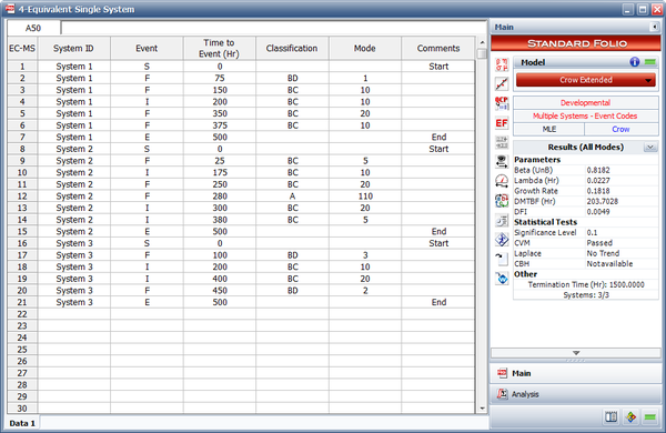
Consider the data set shown in the following figure.
Solution
The first step to creating the equivalent system is to isolate each failure mode and its implemented fixes independently from each other. The numbered steps follow the five rules mentioned in the article Equivalent Single System and are presented in the same numbering sequence.
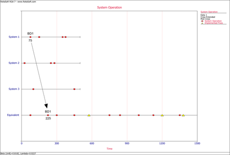
- The next figure illustrates the application of rule #1 for mode BD1. The mode in the equivalent single system is calculated as [math]\displaystyle{ (75+75+75)=225\,\! }[/math] or [math]\displaystyle{ 75*3=225.\,\! }[/math]
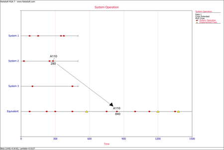
The next figure illustrates the application of rule #1 for mode A110. The mode in the equivalent single system is calculated as [math]\displaystyle{ (280+280+280)=840\,\! }[/math] or [math]\displaystyle{ 280*3=840.\,\! }[/math]
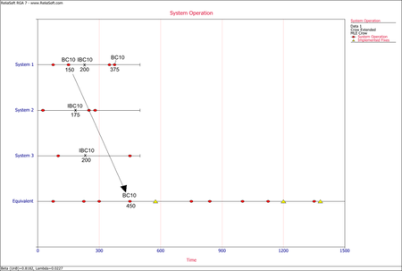
- The next figure illustrates the application of rule #2 for the first occurrence of the mode BC10 in system 1. The mode in the equivalent single system is calculated as [math]\displaystyle{ (150+150+150)=450\,\! }[/math] or [math]\displaystyle{ 150*3=450.\,\! }[/math]
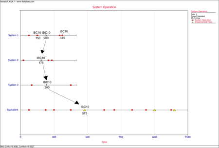
- The next figure illustrates the application of rule #3 for implemented fixes (I events) of the mode BC10. In the graph, the I events are symbolized by having the letter "I" before the naming of the mode. In this case, IBC10 is for the implemented fix of mode BC10. The IBC10 in the equivalent single system is calculated as [math]\displaystyle{ (200+175+200)=575\,\! }[/math].
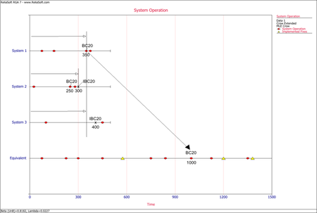
- The next figure illustrates the application of rule #4 for the mode BC20 in system 1, which occurs after a fix for the same mode was implemented in system 2. The mode in the equivalent single system is calculated as [math]\displaystyle{ (350+300+350)=1000.\,\! }[/math]
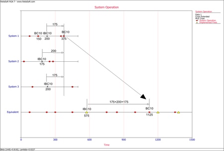
- The next figure illustrates the application of rule #5 for the second occurrence of the mode BC10 in system 1, which occurs after an implemented fix (I event) has occurred for that mode in the same system. The mode in the equivalent single system is calculated as [math]\displaystyle{ 575+(175+200+175)=1125.\,\! }[/math]
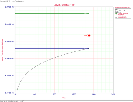
After having transferred the data set to the Crow Extended equivalent system, the data set is analyzed using the Crow Extended model. The last figure shows the growth potential MTBF plot.

