Template:System with Two Standby Blocks (SCT solution)
Two Standby Blocks
Purpose
The purpose of this example is to illustrate how to model a system with two standby devices with SCT.
Statement
Assume that there are four devices A, B, C and D in the system. The system begins with A and B as active devices and C and D as standby devices. At least 2 out of the 4 devices have to be in active status to assure that the system is working. If one of the active device fails, one of standby devices will be activated. After the active device is restored, it will become a standby device. For example, when A fails, C or D will be activated. After A finishes repair, it will become a standby device.
BlockSim Solution
It is easy to model this system with standby containers. However, standby containers have some limitations in other applications. Here we want to model this system with SCT. It is not possible to model this system directly with SCT, so we present an alternative solution which can approximate this system.
The logic is as follows: We will activate all standby devices whenever an active device fails. After activating all standby devices, we will check how many devices are in active status. If there are more than 2 devices in active status, we will deactivate some of them to assure that there are exactly two devices in active status at every moment. The drawback of this solution is that it will activate and deactivate the devices more times than we expected. For example, if A and B are active, then when A fails, it will activate C and D. After activating C and D it will detect that there are three devices in active status, so it will deactivate one of the three active devices: B, C or D. As we can see, it has the chance to deactivate B instead of C, which is not what we expected. If there is extra cost related to activation, this solution is not a good option.
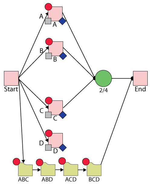
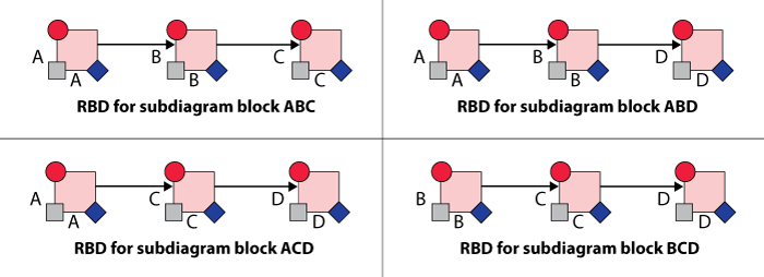
In order to detect that there are more than two devices in active status, we have four subdiagram blocks: ABC, ABD, ACD and BCD. ABC contains mirror blocks A, B and C in series. The RBDs for the main diagram and subdiagram are as shown in the figures below.
Mirror group A includes Block A in the main diagram, Block A in subdiagram ABC, Block A in subdiagram ABD and Block A in subdiagram ACD.
Mirror group B includes Block B in the main diagram, Block B in subdiagram ABC, Block B in subdiagram ABD and Block B in subdiagram BCD.
Mirror group C includes Block C in the main diagram, Block C in subdiagram ABC, Block C in subdiagram BCD and Block C in subdiagram ACD.
Mirror group A includes Block D in the main diagram, Block D in subdiagram ABD, Block D in subdiagram ACD and Block D in subdiagram BCD.
All four blocks (A, B, C and D) follow a Weibull distribution with Beta = 1.5 and Eta = 100 hours for reliability and have CM with duration = 100 hours.
Block A belongs to maintenance group A. It has SCT with initial state ON and state upon repair "Default OFF unless SCT overridden." If any item from maintenance group B, C and D goes down, Block A is activated. If any item from maintenance group ABC is restored, we will deactivate Block A.
Block B belongs to maintenance group B. It has SCT with initial state ON and state upon repair "Default OFF unless SCT overridden." If any item from maintenance group A, C and D goes down, Block B is activated. If any item from maintenance group ABD is restored, we will deactivate Block B.
Block C belongs to maintenance group C. It has SCT with initial state OFF and state upon repair "Default OFF unless SCT overridden." If any item from maintenance group A, B and D goes down, Block C is activated. If any item from maintenance group ACD is restored, we will deactivate Block C.
Block D belongs to maintenance group D. It has SCT with initial state OFF and state upon repair "Default OFF unless SCT overridden." If any item from maintenance group A, B and C goes down, Block D is activated. If any item from maintenance group BCD is restored, we will deactivate Block D.
Subdiagram block ABC belongs to maintenance group ABC. The other three subdiagram blocks each belong to the maintenance group with the corresponding name.


System Events
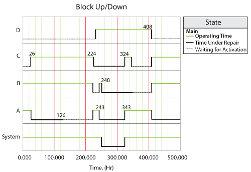
The system event log (simulation seed: 9) is shown Block Up/Down plot below, for a single run through the simulation algorithm and is as follows:
- At 26, Block A fails. Block C and D are activated. However, there are three blocks in active status, thus Block D is deactived immediately.
- At 126, Block A finished its repair. According to settings, Block A is OFF as standby device.
- At 224, Block C fails. Block A and D is activated. However, there are three blocks (A, B, and D) in active status, thus Block B is deactivated immediately. NOTICE: B should not be deactived here, however we cannot control this. This is the drawback of this solution. If there is extra cost related to activation and deactivation, we are wasting of resource by deactivating Block B.
- At 243, Block A fails and activates Block B.
- At 248, Block B fails and this failure try to active Block C and A. However, Block A and C are down at this time. This trigger event is on hold for Block A and C. After Block A and C finish their repair at 324 and 343 respectively, they are ON immediately.
- At 343, Block A finishes its repair. There is a trigger event on hold by failure of Block B at 248. Block A is ON upon repair. At this time, there are three blocks in active status (Block A, C and D), thus Block C is deactivated immediately. This is another evident of wasting resources. The idea case is Block A is deactivate at this moment.
- At 408, Block A fails and activates Block B and C. Since there are three blocks in active status, Block D is deactivated immediately to assure that only two blocks are in active status.
