AND Gate
This page describes the AND gate and it's applications in Fault Tree diagrams used in Reliability and Safety Engineering.
[math]\displaystyle{ }[/math]
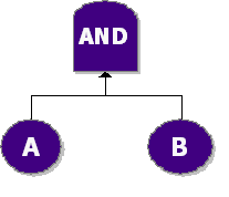
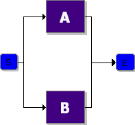
In an AND gate, the output event occurs if all input events occur. In system reliability terms, this implies that all components must fail (input) in order for the system to fail (output). When using RBDs, the equivalent is a simple parallel configuration.
Example
Consider a system with two components, [math]\displaystyle{ A }[/math] and [math]\displaystyle{ B }[/math] . The system fails if both [math]\displaystyle{ A }[/math] and [math]\displaystyle{ B }[/math] fail. Draw the fault tree and reliability block diagram for the system. The next two figures show both the FTD and RBD representations.


The reliability equation for either configuration is:
- [math]\displaystyle{ {{R}_{System}}={{R}_{A}}+{{R}_{B}}-{{R}_{A}}\cdot {{R}_{B}} }[/math]
