Probability of Failure
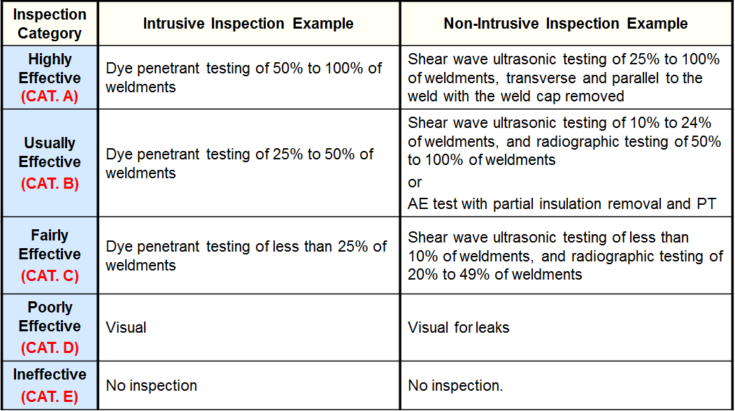
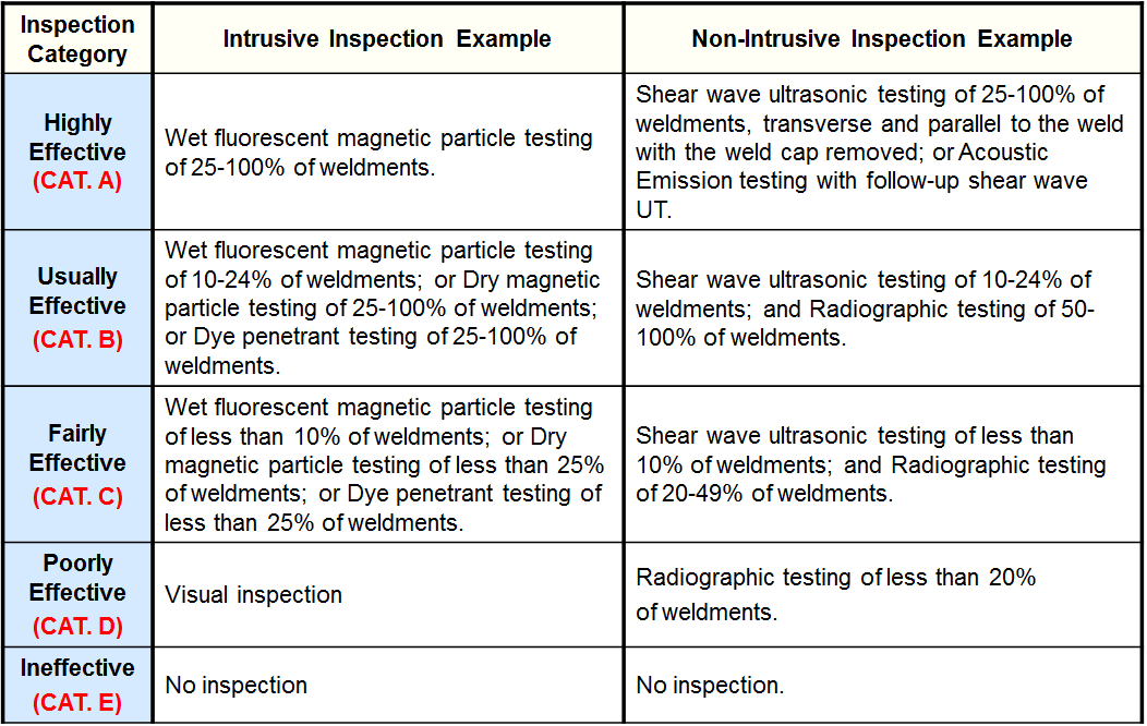
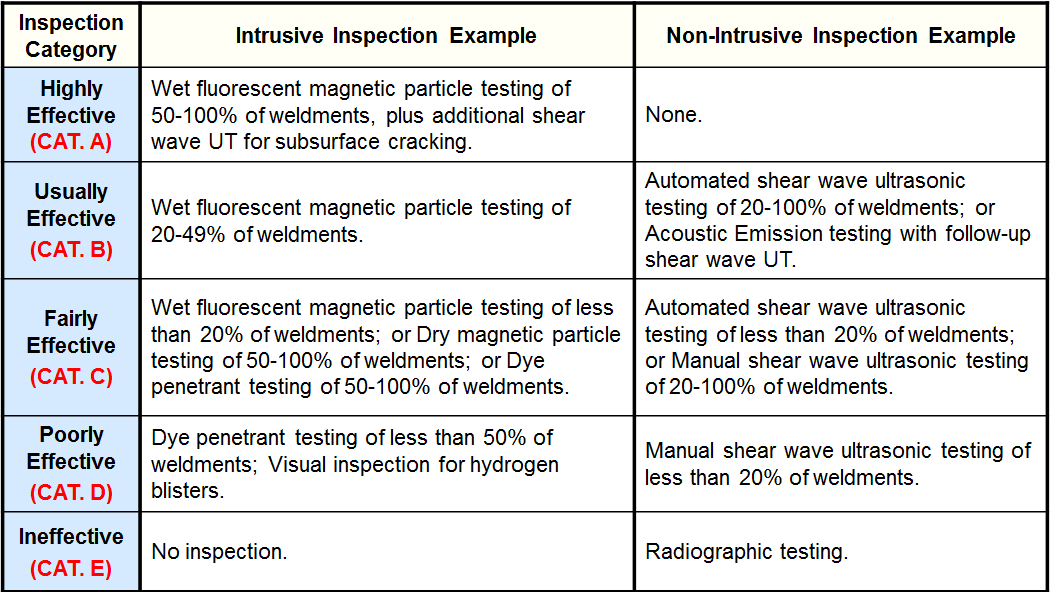
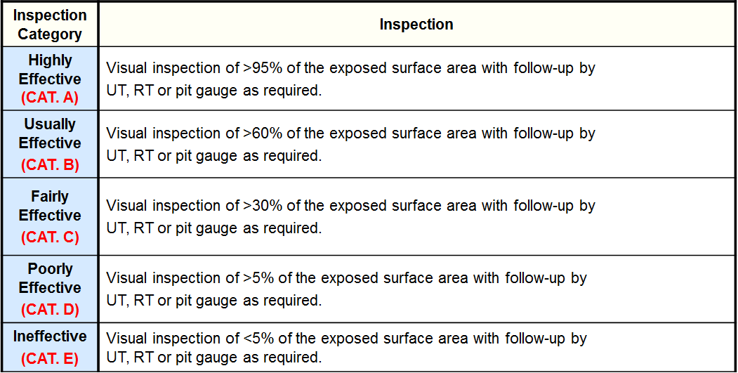
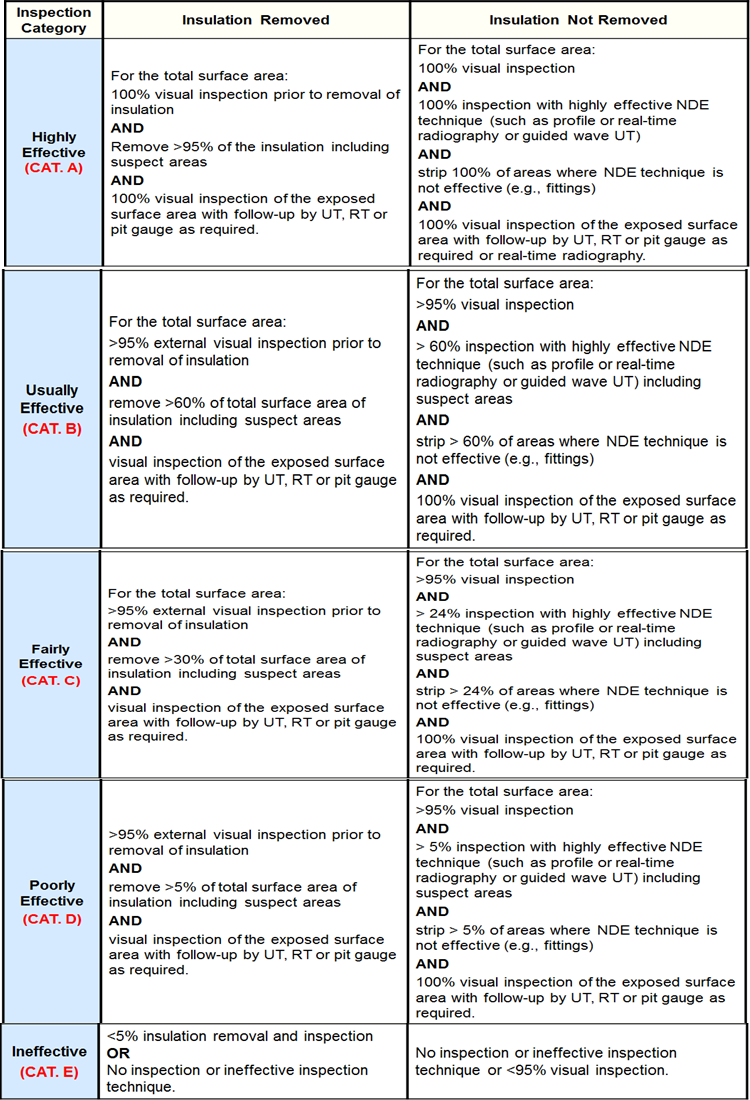
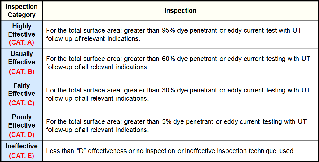
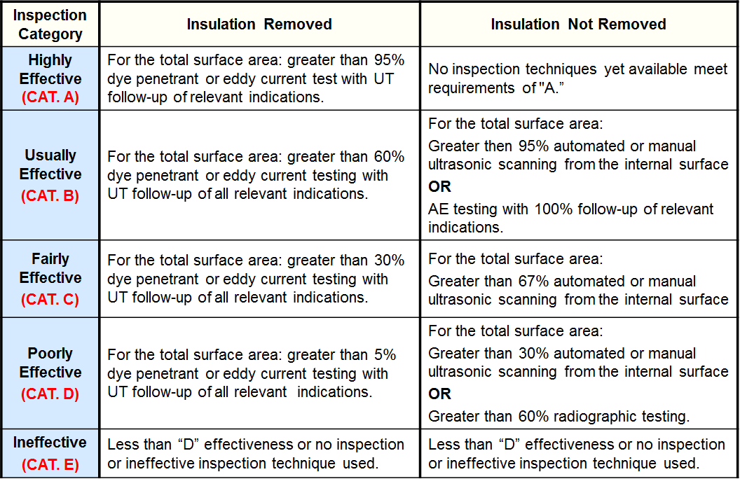
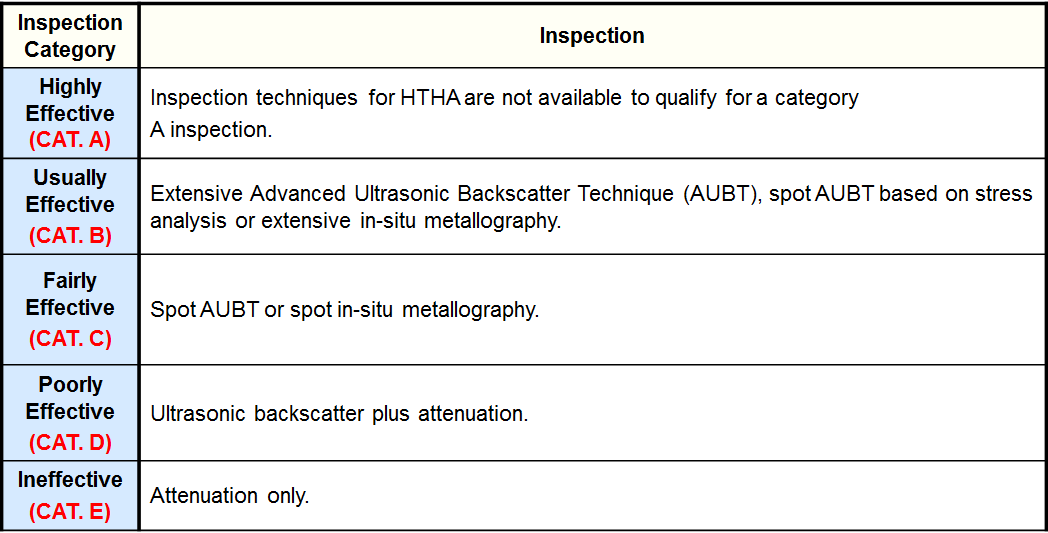
Examples of Inspection Category are from API RP 581 Second Edition September 2008, created by the American Petroleum Institute.
A description of each damage factor used to calculate the probability of failure can be found below.
Thinning Damage Factor
Encompasses general and/or local thinning inside the equipment. All equipment and components are assumed to have or be capable of having damage caused by thinning.
Inspection Effectiveness Categories(General Thinning)
Inspection Effectiveness Categories (General Thinning)
| Inspection Category | Intrusive Inspection Example | Non-Intrusive Inspection Example |
|---|---|---|
| Highly Effective (CAT. A) | 50 to 100% examination of the surface (partial internals removed), and accompanied by thickness measurements. | 50 to 100% ultrasonic scanning coverage (automated or manual) or profile radiography. |
| Usually Effective (CAT. B) | Nominally 20% examination (no internals removed), and spot external ultrasonic thickness measurements. | Nominally 20% ultrasonic scanning coverage (automated or manual), or profile radiography, or external spot thickness (statistically validated). |
| Fairly Effective (CAT. C) | Visual examination with thickness measurements. | 2 to 3% examination, spot external ultrasonic thickness measurements, and little or no internal visual examination. |
| Poorly Effective (CAT. D) | Visual examination. | Several thickness measurements, and a documented inspection planning system. |
| Ineffective (CAT. E) | No inspection. | Several thickness measurements taken only externally, and a poorly documented inspection planning system. |
Inspection Effectiveness Categories(Local Thinning)
Inspection Effectiveness Categories (Local Thinning)
| Inspection Category | Intrusive Inspection Example | Non-Intrusive Inspection Example |
|---|---|---|
| Highly Effective (CAT. A) | 100% visual examination (with removal of internal packing, trays, etc.) and thickness measurements. | 50 to 100% coverage using automated ultrasonic scanning, or profile radiography in areas specified by a corrosion engineer or other knowledgeable specialist. |
| Usually Effective (CAT. B) | 100% visual examination (with partial removal of the internals) including manways, nozzles, etc. and thickness measurements. | 20% coverage using automated ultrasonic scanning, or 50% manual ultrasonic scanning, or 50% profile radiography in areas specified by a corrosion engineer or other knowledgeable specialist. |
| Fairly Effective (CAT. C) | Nominally 50% visual examination and spot ultrasonic thickness measurements. | Nominally 20% coverage using automated or manual ultrasonic scanning, or profile radiography, and spot thickness measurements at areas specified by a corrosion engineer or other knowledgeable specialist. |
| Poorly Effective (CAT. D) | Nominally 20% visual examination and spot ultrasonic thickness measurements. | Spot ultrasonic thickness measurements or profile radiography without areas being specified by a corrosion engineer or other knowledgeable specialist. |
| Ineffective (CAT. E) | No inspection. | Spot ultrasonic thickness measurements without areas being specified by a corrosion engineer or other knowledgeable specialist. |
Inspection Effectiveness Categories (Thinning/Buried Components)
Inspection Effectiveness Categories (Thinning/Buried Components)
| Inspection Category | Intrusive Inspection Example | Non-Intrusive Inspection Example | Non-Intrusive Inspection Example |
|---|---|---|---|
| Highly Effective (CAT. A) | 100% internal inspection via state-of-the-art pigging and in-line inspection technologies (UT, MFL, internal rotary UT, etc.) 100% external inspection of equipment that is only partially buried using an NDE crawler with circumferential inspection technology (MFL, lamb-wave UT). |
Complete excavation, 100% external visual inspection, and 100% inspection with NDE technologies (UT thickness measurement such as handheld devices at close-interval grid locations, UT B-scan, automated ultrasonic scanning, guided-wave UT global search, crawler with circumferential inspection technology such as MFL or lambwave UT, digital radiography in more than one direction). | a) Cathodic Protection (CP) System maintained and managed by NACE certified personnel and complying with NACE SP0169 [14]– includes Stray current surveys on a regular basis. b) Close Interval Survey (at excavation sites) to assess the performance of the CP system locally. c) Sample soil and water resistivity and chemistry measurements along entire structure. |
| Usually Effective (CAT. B) | Internal inspection via pigging and in-line inspection technologies (UT, MFL, internal rotary UT, etc.) of selected areas/sections, combined with statistical analysis or extreme value analysis (EVA). External inspection of equipment that is only partially buried using an NDE crawler with circumferential inspection technology (MFL, lambwave UT) on selected areas/sections, combined with statistical analysis or extreme value analysis (EVA). |
Excavation at "Selected" locations, 100% external visual, and 100% inspection with NDE technologies (UT thickness measurement such as handheld devices at close-interval grid locations, UT B-scan, automated ultrasonic scanning, guided-wave UT global search, crawler with circumferential inspection technology such as MFL or lambwave UT, digital radiography in more than one direction). | a) CP System maintained and managed by NACE certified personnel and complying with NACE SP0169 [14] – includes Stray current surveys on a regular basis. b) Close Interval Survey (at excavation sites) to assess the performance of the CP system locally. c) Sample soil and water resistivity and chemistry. d) Measurements along entire structure. e) DC Voltage Gradient (DCVG) to determine coating damage. |
| Fairly Effective (CAT. C) | Partly inspection by internal smart pig or specialized crawler device, including a representative portion of the buried pipe. (<25%). | Partial excavation guided-wave UT global search inspection in each direction of pipe. Corrosion Inspection and Maintenance managed by NACE certified and CP specialist, or equivalent. | - |
| Poorly Effective (CAT. D) | Hydrostatic testing. | Spot check with conventional NDE equipment of local areas exposed by excavation. | - |
| Ineffective (CAT. E) | No inspection. | - | - |
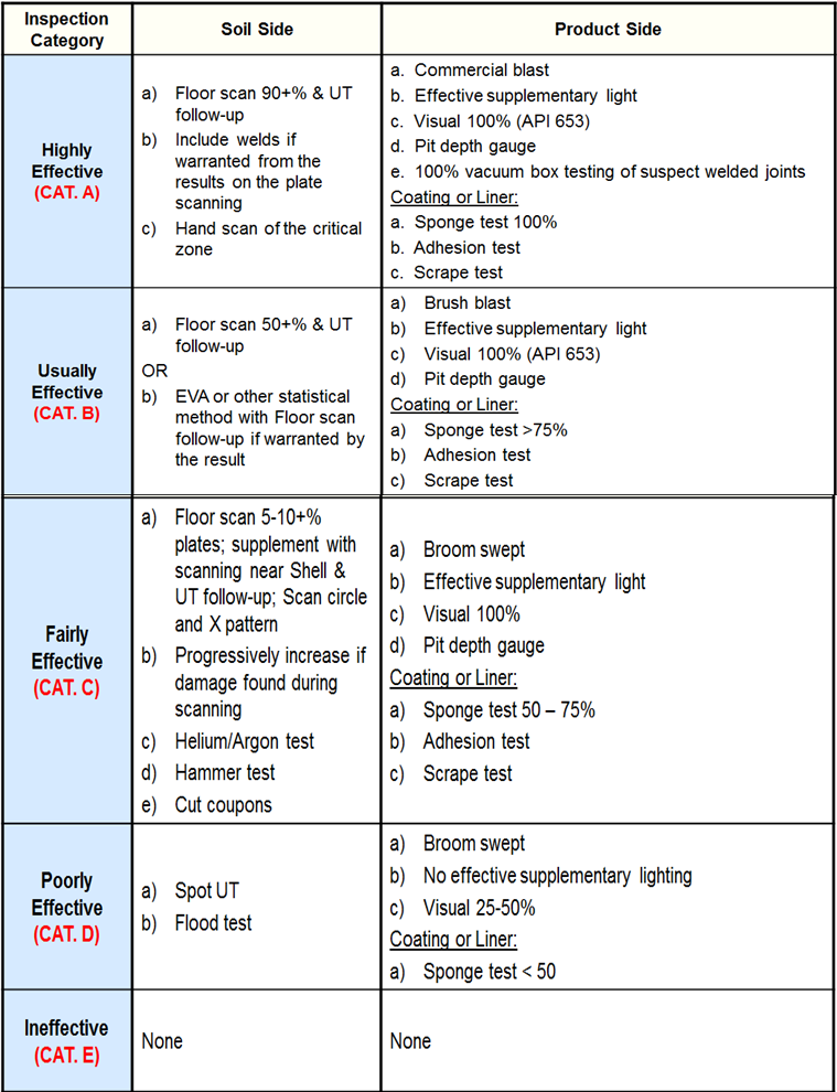
Inspection Effectiveness Categories (Thinning/Tank Bottoms)
Inspection Effectiveness - Tank Shell Course Internal Corrosion
Inspection Effectiveness – Tank Shell Course Internal Corrosion
| Inspection Category | Inspection |
|---|---|
| Highly Effective (CAT. A) |
a) Intrusive inspection – good visual inspection with pit depth gauge measurements at suspect locations.
b) UT scanning follow up on suspect location and as general confirmation of wall thickness. |
| Usually Effective (CAT. B) |
a) External spot UT scanning based on visual information from previous internal inspection of this tank or similar service tanks.
b) Internal video survey with external UT follow-up. |
| Fairly Effective (CAT. C) |
External spot UT scanning based at suspect locations without benefit of any internal inspection information on tank type or service. |
| Poorly Effective (CAT. D) |
External spot UT based at suspect locations without benefit of any internal inspection information on tank type or service. |
| Ineffective (CAT. E) |
No inspection. |
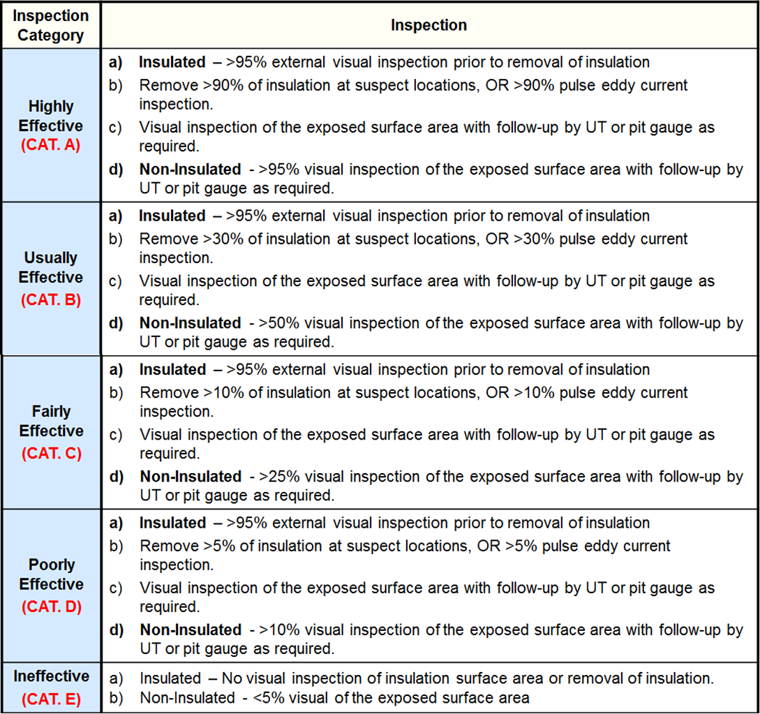
Inspection Effectiveness - Tank Shell Course External Corrosion
Component Lining Damage Factor
An equipment or component may have lining damage. Linings of inorganic and organic origins can be deteriorated, usually because of corrosion.
The Lining Damage Factor does not have Inspection Effectiveness Categories. It can either be inspected or not be inspected.
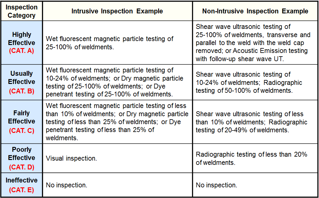
Stress Corrosion Cracking (SCC) Damage Factor- Caustic Cracking
Caustic Cracking is the combined action of tensile stress and corrosion in the presence of NaOH at elevated temperature.
- Cracking is predominantly intergranular and typically occurs as a network of fine cracks in carbon steels. Low alloy steels have similar cracking susceptibility.
- There are three key parameters:
- Caustic concentration,
- Metal temperature
- Level of tensile stress
- Caustic cracking of carbon steel is not anticipated at metal temperatures less than about 46°C. Between 46°C and 82°C, it is a function of caustic concentration. Above 82°C it is highly likely for all concentratios above about 5 wt%.
- Metal temperature is the key parameter and not the process temperature. Cases of components at ambient temperature that were heat traced or subject to a steam out while containing caustic.
- Post Weld Heat Treatment (PWHT) is a proven method to prevent caustic cracking.
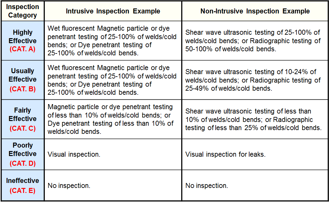
Inspection Effectiveness - Caustic Cracking
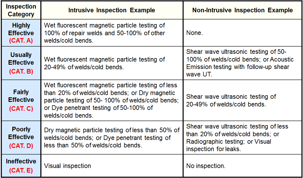
Stress Corrosion Cracking (SCC) Damage Factor- Amine Cracking
Amine Cracking is the combined action of tensile stress and corrosion in the presence of an aqueous alkanolamine at elevated temperature.
- Cracking is predominantly intergranular and typically occurs as a network of fine cracks in carbon steels. Low alloy steels have similar cracking susceptibility.
- The four key parameters:
- Type of amine
- Amine solution composition
- Metal temperature
- Level of tensile stress.
- Amine cracking is not anticipated in fresh amine solutions that have not been exposed to acid gases or in rich alkanolamine solutions which contain high levels of acid gases, but mostly in lean alkanolamine solutions which contain low levels of acid gases.
- Metal temperature is the key parameter and not the process temperature. Cases of components at ambient temperature that were heat traced or subject to a steam out while containing caustic.
- Post Weld Heat Treatment (PWHT) is a proven method to prevent amine cracking.
Inspection Effectiveness Categories (Amine Cracking)
Stress Corrosion Cracking (SCC) Damage Factor- Sulfide Stress Cracking
Sulfide Stress Cracking is the combined action of tensile stress and corrosion in the presence of water and hydrogen sulfide.
- There are four key parameters
- Metal hardness
- Stress Level
- pH
- H2S content of process fluid
- Sulfide stress cracking is more prevalent in high hardness metals, with the hydrogen flux being lowest at neutral pH and increasing at both lower and higher pHs.
- Cyanide presence at high pH can increase the hydrogen flux into the steel.
- Source of hydrogen in the steel is the corrosion reaction with wet hydrogen sulfide in the presence of water.
- Post Weld Heat Treatment (PWHT) is a proven method to prevent sulfide stress cracking.
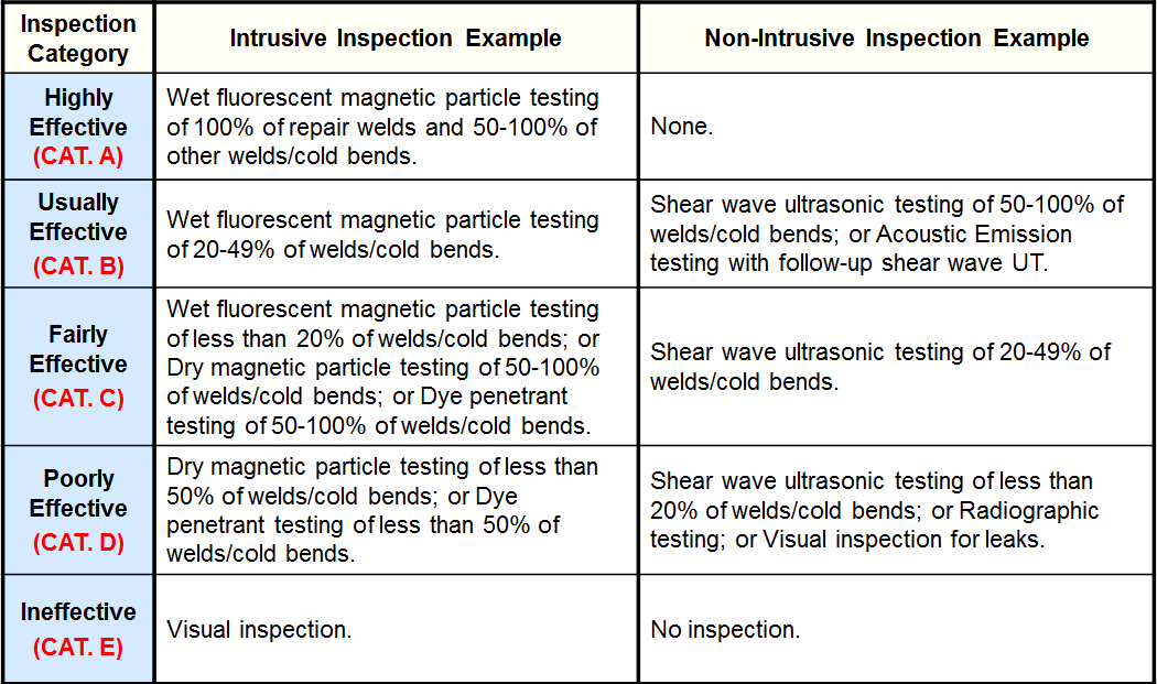
Inspection Effectiveness - Sulfide Stress Cracking
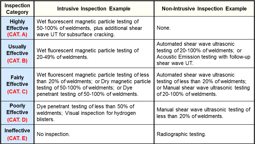
Stress Corrosion Cracking (SCC) Damage Factor- HIC/SOHIC-H2S
H2S components are subject to hydrogen-induced cracking and stress-oriented hydrogen induced cracking in H2S services.
- Internal cracks can connect adjacent hydrogen blisters on different planes on the metal surface.
- External applied stress does not always exist.
- Driving force is high stresses at the circumference of the hydrogen blisters that are caused by buildup of internal pressure.
- Buildup of blister pressure is related to the hydrogen permeation flux in the steel.
- Source of hydrogen in the steel is the corrosion reaction with wet hydrogen sulfide in the presence of water.
- Corrosion at low pH values is caused by H2S, whereas corrosion at high pH values is caused by high concentrations of bisulfide ion.
- Cyanides at elevated pH can aggravate hydrogen penetration into the steel.
- Presence of 50 ppm of H2S in the water is sufficient to cause HIC.
- Sulfur content of the steel is a key parameter for the susceptibility. Reducing the sulfur content of the steel reduces the susceptibility to blistering. Additions of calcium or REMS (rare-earth elements) which control sulfide inclusion are generally beneficial.
- Cleanliness of the steel is measured by the sulfur content.
- Blistering does pose a danger to mechanical integrity when it approaches a weld which contains sufficient residual stresses.
- SOHIC is a stacked array of blisters joined by hydrogen-induced cracking aligned in the through-thickness direction of the steel as a result of high localized tensile stresses.
- Reduction of residual stresses by PWHT can reduce the occurrance and severity of SOHIC.
Inspection Effectiveness - HIC/SOHIC-H2S
Stress Corrosion Cracking (SCC) Damage Factor- Carbonate Cracking
- Combined action of tensile stress and corrosion in the presence of an alkaline sour water containing CO3.
- Cracking is predominantly intergranular and typically occurs as a network of fine cracks in carbon steels. Low alloy steels have similar cracking susceptibility.
- Three key parameters:
- pH of the sour water
- Carbonate concentration
- Level of tensile stress
- Carbonate cracking occurs in a narrow range of electrochemical potential, which is caused by moderate to high levels of carbonates in alkaline sour water.
- Cyanide presence influences cracking susceptibility.
- PWHT is a proven method to prevent amine cracking.
Inspection Effectiveness Categories- Carbonate Cracking
Stress Corrosion Cracking (SCC) Damage Factor- PTA Cracking
- Combined action of tensile stress with the presence of sulfide containing deposits during shutdown.
- Cracking is always intergranular and requires low tensile stresses for initiation and propagation.
- Four key parameters: presence of sulfide, exposure to air and moisture during shutdown, carbonate concentration and level of tensile stress.
- PTA cracking is often found in as-welded stainless steels, particularly in the weld heat-affected zone.
- Downtime protection according to NACE RP0170 reduces the risk of PTA cracking.
Inspection Effectiveness Categories- PTA Cracking
Stress Corrosion Cracking (SCC) Damage Factor- CLSCC
- Occurs to austenitic stainless steel components in chloride containing aqueous environments.
- Cracking is predominantly intergranular and highly branched.
- Three key parameters: pH of the process fluid, chloride ion concentration and temperature.
- CLSCC is most prevalent in austenitic SS with an 8% nickel content. Lower or higher nickel content SS shows greater resistance, with Duplex SS with a low nickel content or alloys with greater than 42% nickel content being generally immune to CLSCC.
Inspection Effectiveness Categories- SCC CLSCC
Stress Corrosion Cracking (SCC) Damage Factor- HSC-HF
- Components are subject to hydrogen-induced cracking and stress-oriented hydrogen induced cracking in HF services.
- Source of hydrogen in the steel is the corrosion reaction with hydrofluoric acid.
- Internal cracks can connect adjacent hydrogen blisters on different planes on the metal surface.
- External applied stress does not always exist.
- Driving force is high stresses at the circumference of the hydrogen blisters that are caused by buildup of internal pressure.
- Buildup of blister pressure is related to the hydrogen permeation flux in the steel. Blistering does pose a danger to mechanical integrity when it approaches a weld which contains sufficient residual stresses.
Inspection Effectiveness Categories- SCC HSC-HF
Stress Corrosion Cracking (SCC) Damage Factor- HIC/SOHIC-HF
- Cleanliness of the steel is measured by the sulfur content. Reducing the sulfur content of the steel reduces the susceptibility to blistering. Additions of calcium or REMS (rare-earth elements) which control sulfide inclusion are generally beneficial.
- SOHIC is a stacked array of blisters joined by hydrogen-induced cracking aligned in the through-thickness direction of the steel as a result of high localized tensile stresses.
- Reduction of residual stresses by PWHT can reduce the occurrance and severity of SOHIC.
Inspection Effectiveness Categories- SCC HIC/SOHIC-HF
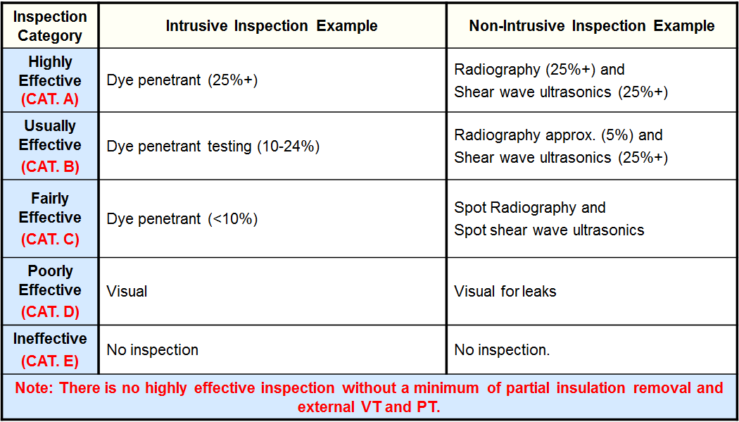
External Corrosion Damage Factor- Ferritic Component
- Plants located in areas where an accumulation of chloride can result from local conditions or units located in the mist areas of cooling towers or steam vents can be subject to external CLSCC.
- Cracking is predominantly intergranular and highly branched.
- Two key parameters: chloride ion concentration and temperature.
CLSCC is most prevalent in austenitic SS with an 8% nickel content. Lower or higher nickel content SS shows greater resistance, with Duplex SS with a low nickel content or alloys with greater than 42% nickel content being generally immune to CLSCC.
- Mitigation is accomplished by preventing chloride buildup on the SS surface.
Inspection Effectiveness Categories- External -Ferritic Component
CUI Damage Factor- Ferritic Component
- Plants located in areas with high annual rainfall, warmer climate or marine locations are more prone to external corrosion than those located in cooler, drier areas.
- Units located near cooling towers and steam vents or those whose operating temperatures cycle through the dew point on a regular basis are highly susceptible to external corrosion regardless of climate.
- Proper painting/coating of the component surface is an accomplished method of mitigation for external corrosion.
Inspection Effectiveness Categories- CUI -Ferritic Component
External CLSCC Damage Factor- Austenitic Component
- Plants located in areas where an accumulation of chloride can result from local conditions or units located in the mist areas of cooling towers or steam vents can be subject to external CLSCC.
- Cracking is predominantly intergranular and highly branched.
- Two key parameters:
- Chloride ion concentration
- Temperature.
CLSCC is most prevalent in austenitic SS with an 8% nickel content. Lower or higher nickel content SS shows greater resistance, with Duplex SS with a low nickel content or alloys with greater than 42% nickel content being generally immune to CLSCC.
- Mitigation is accomplished by preventing chloride buildup on the SS surface.
Inspection Effectiveness Categories- CLSCC -Austenitic Component
External CUI CLSCC Damage Factor- Austenitic Component
- Plants located in areas where an accumulation of chloride can result from local conditions or units located in the mist areas of cooling towers or steam vents can be subject to external CUI CLSCC. Even the insulation itself can be a source of chloride.
- Cracking is predominantly intergranular and highly branched.
- Two key parameters:
- Chloride ion concentration
- Temperature
CLSCC is most prevalent in austenitic SS with an 8% nickel content. Lower or higher nickel content SS shows greater resistance, with Duplex SS with a low nickel content or alloys with greater than 42% nickel content being generally immune to CLSCC.
- Mitigation is accomplished by preventing chloride buildup on the SS surface under the insulation or with the use of coating or wrapping of the component in aluminum foil.
Inspection Effectiveness Categories- CUI CLSCC -Austenitic Component
HTHA Damage Factor
- Components exposed to high temperatures and high hydrogen partial pressures are susceptible to high temperature hydrogen attack (HTHA).
- Damage is either internal decarburization and fissuring due to accumulated methane gas or just surface decarburization when methane gas can escape.
- Two key parameters:
- Partial pressure of hydrogen
- Temperature.
- HTHA is prevalent in carbon steels, C-0.5Mo, and Cr-Mo low alloy steels. Carbon steel that only contains Fe3C carbides has less resistance to HTHA than those that contain Cr-Mo carbides.
- Mitigation is accomplished by increasing the alloy content of the steel and therefore increasing the stability of the carbides.
Inspection Effectiveness Categories- HTHA
Brittle Fracture Damage Factor
- Components exposed to temperatures below their Minimum Design Metal Temperatures (MDMT) are susceptible to brittle fracture.
- Damage is usually initiated at a crack or defect due to low temperatures or low toughness.
- Three key parameters:
- Temperature
- Thickness
- Stress
- Brittle fracture is prevalent in carbon or low alloy steel where the unit operates at temperatures below the MDMT during normal or upset conditions.
- Mitigation is accomplished by temperature control to ensure that the component is not subjected to temperatures below the MDMT while at operating pressures. Brittle fracture is typically not relevant above 150°C.
This damage factor cannot be detected by inspection.
Temper Embrittlement Damage Factor
- Components exposed to operating temperatures between 343°C and 577°C for extended periods of time may be subject to temper embrittlement.
- Damage is usually initiated along the grain boundaries in the steel due to segregation of tramp and alloying elements.
- Three key parameters:
- Temperature,
- Thickness
- Tramp/alloying elements.
- Temper Embrittlement is prevalent in low alloy steels, especially for weld metals and heat affected zones.
- Post Weld Heat Treatment (PWHT) lowers the susceptibility to temper embrittlement.
This damage factor cannot be detected by inspection.
885 Embrittlement Damage Factor
- Components exposed to operating temperatures between 371°C and 566°C for extended periods of time may be subject to 885 embrittlement.
- Damage is usually initiated by the precipitation of the intermetallic phase (chromium-phosphorous), leading to a reduction in toughness.
- Two key parameters:
- Temperature
- Chromium content.
- 885 embrittlement is prevalent in high chromium ferritic steels, especially around 474°C (885°F) and with more than 27% chromium content.
- 885 embrittlement is reversible by heat treatment to dissolve precipitates, followed by rapid cooling. However, heat treatment is typically in the 760°C to 816°C range, which may not be possible for some components.
This damage factor cannot be detected by inspection.
Sigma Phase Embrittlement Damage Factor
- Components exposed to operating temperatures between 593°C and 927°C for more than a few hours maybe subject to sigma phase embrittlement.
- Damage is usually initiated by the formation of a sigma phase, a brittle intermetallic compound, leading to loss of toughness which can lead to fracture under stress or impact during shutdown.
- Three key parameters:
- Temperature,
- Composition
- Cold work history of the steel.
- Sigma phase embrittlement is prevalent in compounds of iron and chromium, especially with compositions around 60% iron and 40% chromium. Danger arises from the possibility of transformation to roughly 100% sigma phase.
- Sigma phase is unstable above 899°C, thus austenitic stainless steel can be de-sigmatized by solution annealing at 1066°C for four hours followed by a water quench.
This damage factor cannot be detected by inspection.
Piping Mechanical Fatigue Damage Factor
- Components that are pipes and are subject to shaking or cyclic vibration or have a history of past fatigue failures are susceptible to piping mechanical fatigue.
- Damage is usually initiated by cracks formed during the initiation phase that grow due to shaking and vibration.
- Three key parameters:
- History of fatigue
- Visible/audible shaking
- Cyclic vibration
- Mitigation depends heavily on detection and correction of conditions that lead to mechanical fatigue.
This damage factor cannot be detected by inspection.

