Template:Reliability block diagrams for failure modes: Difference between revisions
(Created page with '= Reliability Block Diagrams for Failure Modes and Other Applications = In this reference, most of the examples and derivations assume that each block represents a component/suba…') |
Pengying niu (talk | contribs) |
||
| Line 10: | Line 10: | ||
Analysis of this diagram follows the same principles as the ones presented in this chapter and can be performed in BlockSim, if desired. | Analysis of this diagram follows the same principles as the ones presented in this chapter and can be performed in BlockSim, if desired. | ||
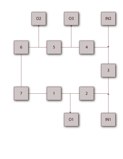
[[Image:chp4image33.png|thumb|center|400px|Electircal network diagram.]] | [[Image:chp4image33.png|thumb|center|400px|Fig 4.25 Electircal network diagram.]] | ||
<br> | <br> | ||
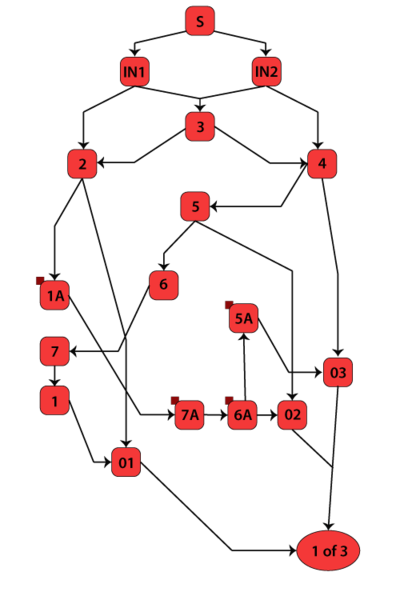
[[Image:chp4image34.png|thumb|center|400px|RBD of the network in Figure 4.25.]] | [[Image:chp4image34.png|thumb|center|400px|Fig 4.26 RBD of the network in Figure 4.25.]] | ||
<br> | <br> | ||
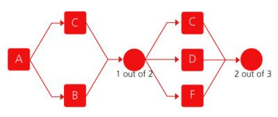
[[Image:chp4image35.png|thumb|center|400px|Reliability block diagram for Example 17.]] | [[Image:chp4image35.png|thumb|center|400px|Fig 4.27 Reliability block diagram for Example 17.]] | ||
<br> | <br> | ||
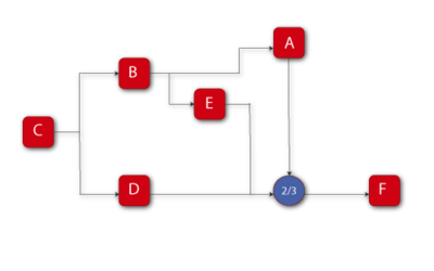
[[Image:chp4image36.png|thumb|center|400px|Reliability block diagram for Example 18.]] | [[Image:chp4image36.png|thumb|center|400px|Fig 4/28 Reliability block diagram for Example 18.]] | ||
<br> | <br> | ||
Revision as of 19:06, 7 February 2012
Reliability Block Diagrams for Failure Modes and Other Applications
In this reference, most of the examples and derivations assume that each block represents a component/subassembly in a larger system. The same methodology and principles can also be used for other applications. For example, all derivations assume that the event under consideration is the event of failure of a component. One can easily take this principle and apply it to failure modes for a component/subsystem or system. To illustrate this, consider the following example.
Example 17
Assume that a system has five failure modes: A, B, C, D and F. Furthermore, assume that failure of the entire system will occur if mode A occurs, modes B and C occur simultaneously or if either modes C and D, C and F or D and F occur simultaneously. Given the probability of occurrence of each mode, what is the probability of failure of the system?
Figure 4.27 shows the diagram for this configuration.
Analysis of this diagram follows the same principles as the ones presented in this chapter and can be performed in BlockSim, if desired.
Example 18
Assume that a system has six failure modes: A, B, C, D, E and F. Furthermore, assume that failure of the entire system will occur if:
- • Mode B, C or F occurs.
- • Modes A and E, A and D or E and D occur.
Draw the block diagram and obtain the reliability equation.
Solution to Example 18
The diagram is shown in Figure fig35
The reliability equation, as obtained from BlockSim is:
- [math]\displaystyle{ \begin{align} {{R}_{System}}= & (-2{{R}_{A}}\cdot {{R}_{B}}\cdot {{R}_{C}}\cdot {{R}_{D}}\cdot {{R}_{2/3}}\cdot {{R}_{E}}\cdot {{R}_{F}} \\ & +{{R}_{A}}\cdot {{R}_{B}}\cdot {{R}_{C}}\cdot {{R}_{D}}\cdot {{R}_{2/3}}\cdot {{R}_{F}} \\ & +{{R}_{A}}\cdot {{R}_{B}}\cdot {{R}_{C}}\cdot {{R}_{2/3}}\cdot {{R}_{E}}\cdot {{R}_{F}} \\ & +{{R}_{B}}\cdot {{R}_{C}}\cdot {{R}_{D}}\cdot {{R}_{2/3}}\cdot {{R}_{E}}\cdot {{R}_{F}}) \end{align} }[/math]
The BlockSim equation includes the node reliability term [math]\displaystyle{ {{R}_{2/3}}, }[/math] which cannot fail, or [math]\displaystyle{ {{R}_{2/3}}=1 }[/math] . This can be removed, yielding:
- [math]\displaystyle{ \begin{align} {{R}_{System}}= & (-2{{R}_{A}}\cdot {{R}_{B}}\cdot {{R}_{C}}\cdot {{R}_{D}}\cdot {{R}_{E}}\cdot {{R}_{F}} \\ & +{{R}_{A}}\cdot {{R}_{B}}\cdot {{R}_{C}}\cdot {{R}_{D}}\cdot {{R}_{F}} \\ & +{{R}_{A}}\cdot {{R}_{B}}\cdot {{R}_{C}}\cdot {{R}_{E}}\cdot {{R}_{F}} \\ & +{{R}_{B}}\cdot {{R}_{C}}\cdot {{R}_{D}}\cdot {{R}_{E}}\cdot {{R}_{F}}) \end{align} }[/math]


