Voting OR Gate Example
 |
New format available! This reference is now available in a new format that offers faster page load, improved display for calculations and images and more targeted search.
As of January 2024, this Reliawiki page will not continue to be updated. Please update all links and bookmarks to the latest references at BlockSim examples and BlockSim reference examples.
This example also appears in the System Analysis Reference book.
Voting OR Gate

In a Voting OR gate, the output event occurs if [math]\displaystyle{ k\,\! }[/math] or more of the input events occur. In system reliability terms, this implies that if any k-out-of-n components fail (input) then the system will fail (output).
The equivalent RBD construct is a node and is similar to a k-out-of-n parallel configuration with a distinct difference, as discussed next. To illustrate this difference, consider a fault tree diagram with a 2-out-of-4 Voting OR gate, as shown in the following figure.

In this diagram, the system will fail if any two of the blocks below fail. Equivalently, this can be represented by the RBD shown in the next figure using a 3-out-of-4 node.

In this configuration, the system will not fail if three out of four components are operating, but will fail if more than one fails. In other words, the fault tree considers k-out-of-n failures for the system failure while the RBD considers k-out-of-n successes for system success.
Increasing the Flexibility
Classical Voting OR gates have no properties and cannot fail or be repaired (i.e., they cannot be an event themselves). In BlockSim, Voting OR gates behave like nodes in an RBD; thus, they can also fail and be repaired just like any other event. By default, when a Voting OR gate is inserted into a fault tree diagram within BlockSim, the gate is set so that it cannot fail (classical definition). However, this property can be modified to allow for additional flexibility.
Example
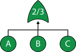
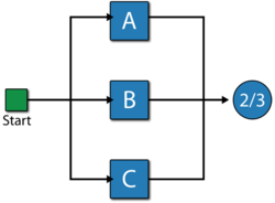
Consider a system with three components, A, B and C. The system fails if any two components fail. Draw the fault tree and reliability block diagram for the system. The next two figures show both the FTD and RBD representations.
The reliability equation for either configuration is:
- [math]\displaystyle{ {{R}_{System}}=-2\cdot {{R}_{A}}\cdot {{R}_{B}}\cdot {{R}_{C}}+{{R}_{A}}\cdot {{R}_{B}}+{{R}_{A}}\cdot {{R}_{C}}+{{R}_{B}}\cdot {{R}_{C}}\,\! }[/math]
Equation above assumes a classical Voting OR gate (i.e., the voting gate itself cannot fail). If the gate can fail then the equation is modified as follows:
- [math]\displaystyle{ {{R}_{System}}={{R}_{Voting}}\left( -2\cdot {{R}_{A}}\cdot {{R}_{B}}\cdot {{R}_{C}}+{{R}_{A}}\cdot {{R}_{B}}+{{R}_{A}}\cdot {{R}_{C}}+{{R}_{B}}\cdot {{R}_{C}} \right)\,\! }[/math]
Note that while both the gate and the node are 2-out-of-3, they represent different circumstances. The Voting OR gate in the fault tree indicates that if two components fail then the system will fail; while the node in the reliability block diagram indicates that if at least two components succeed then the system will succeed.