BlockSim Analytical Fault Tree Diagram Example: Difference between revisions
Jump to navigation
Jump to search
No edit summary |
No edit summary |
||
| Line 1: | Line 1: | ||
{| class="FCK__ShowTableBorders" border="0" cellspacing="0" cellpadding="0" align="center"; style="width:100%;" | {| class="FCK__ShowTableBorders" border="0" cellspacing="0" cellpadding="0" align="center"; style="width:100%;" | ||
|- | |- | ||
| valign="middle" align="left" bgcolor=EEEDF7|[[Image: | | valign="middle" align="left" bgcolor=EEEDF7|[[Image:BlockSim-Examples-banner.png.png|500px|center]] | ||
|} | |} | ||
Revision as of 18:40, 21 March 2012
Example
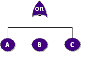
Consider a system with three components, [math]\displaystyle{ A, }[/math] [math]\displaystyle{ B }[/math] and [math]\displaystyle{ C }[/math] . The system fails if [math]\displaystyle{ A, }[/math] [math]\displaystyle{ B }[/math] or [math]\displaystyle{ C }[/math] fails. Draw the fault tree and reliability block diagram for the system. The next two figures show both the FTD and RBD representations.
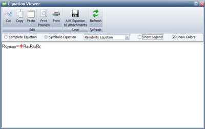
The reliability equation for either configuration is:
- [math]\displaystyle{ {{R}_{System}}={{R}_{A}}\cdot {{R}_{B}}\cdot {{R}_{C}} }[/math]
Figure below show the analytic equation from BlockSim 8.


